NJH.PORTFOLIO
BLDS
Boundary Layer Data system
This project was done in fulfillment of my Master's Thesis in Mechanical Engineering at Cal Poly. I was tasked with continuing the work from an ongoing project team the Boundary Layer Data System (BLDS) to create a new module the BLDS-M-RAKE. I redesigned the PCB, software, plumbing, and housing.
Typically when measurements need to be made on the outside of the plane, it has to be taken out of rotation and the measurement probe is installed. The measurement probe necessitates cutting holes in the skin of the plane, which needs lots of approvals and time. This probe is connected by wires to a box in a rack in the main body of the aircraft. This box is always monitored by a test operations technician/engineer during the flight, so you are limited on the amount of sensors/things you can test by how many people can fit in the body of the aircraft. This whole process takes months (or years), many man hours, and money.
BLDS has a few fully functional autonomous measurement suites that attach to whatever you need to get boundary layer data from. Typically clients want pressures from a rake or skin friction probes, but other measurements have been done. By design, they weigh less than 1lb and have small aerodynamic profiles. Depending on the configuration, they are roughly bounded by a .5 x 7 x 4.5 inch box. This measurement suite is then glued to the surface with a special strong removable adhesive and additionally taped down, mitigating the typical flight test issues discussed above.
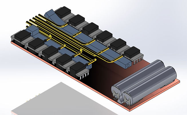
OVERALL PCB AND PLUMBING CAD
This shows the general layout of the large components to be populated on the board along with plumbing. Each pressure sensor is hooked into a flexible silicone manifold (blue) on their bottom port, their top port connects to a brass tube routed to the front of the board for ease of access. AAA batteries power the board.

STUFFED BOARD
The new BLDS board includes: (10) differential sensors, (1) absolute sensor, (2) AAA batteries, DC-DC converter, USB to serial bridge to talk to the board from PC, SD card reader, and Simblee chip. All of this is modularly programmed in C++ using multitasking and state machines that referenced drivers. I used Arduino IDE to increase accessibility for future student work.
MANIFOLD LEAK CHECK TEST
In the design of the manifolds I ran tests, culminating in a final leak check to verify that this would work for our application. Shown is a two sensor manifold holding a -1 psi vacuum for 2 minutes.
